The vacation grounds of upstate New York, particularly the Adirondack area suffer from poor cellular service.
Recent fatal accidents have left the public blaming the lack of cell phone coverage for slow emergency response.
There are a few things professional users (including volunteer emergency services) and prosumers can do to improve in-car cellular service.
Readily available technology yields:
3-watt cell phone automotive/RV/SOHO bidirectional amplifiers (direct or wireless coupling to handset) greatly improve coverage over the internal antenna cell phone
900 MHz long-range cordless phone covers large home / country estate and higher-power units cover campgrounds and remote worksites
outdoor WiFi APs will blanket several acres of worksite/campground with 802.11 2.4 GHz WiFi for modern phones and laptops.
There isn’t any fundamental difference in radio waves between two-way radio and cellular.
The ubiquitous handheld cell phones with internal antennas suffer several dB disadvantage vs. older handheld phones with external antennas.
Add several more dB penalty for handheld cell phone used in car or building.
Cellular coverage can be significantly augmented by using bidirectional amplifiers in the home, office or vehicle.
However, terrain in mountainous areas precludes 100% coverage.
Automobile-installed cellular phone repeaters and amplifiers
can yield up to 3 Watts output power from your car back to the tower, just like traditional bag phones.
The bidirectional amplifier costs about $200-$300, the phone adapter another $20, and the install probably $100-$200.
This could be a life-saver or at least a time-saver in remote areas.
The cellular signal is attenuated by more than 10 dB in both directions with a handheld phone in the car compared to an external antenna.
However, in mountainous terrain, oftentimes the problem is simply terrain blockage, so sometimes no amount of hardware will help.
This is where emergency services use their own VHF/UHF repeater towers to fill the cellular gaps via radio.
Burning Man 2007 saw the debut of standalone cellular service via USRP OpenBTS.
OpenBTS can cover remote worksites and campgrounds with cellular, when the provider’s network doesn’t yield coverage.
Bidirectional amplifiers can have 20-80 dB of gain depending on the model.
The lower gain (< 40 dB) models assume the phone is within about 10 meters of the amplifier–and that with a good signal at the donor amplifier.
If the phone already does not have an adequate signal, then a high-gain donor antenna placed up high is required.
To cover outdoor areas with bidirectional amplifier, free-space loss and antenna pattern analysis shows that the isolation distance required is large enough to require fiber optic interconnection to be practical.
This translates to significant expense, probably excessive for a large number of campgrounds and remote outdoor worksites.
Telephone and data coverage to campsites and remote outdoor worksites can consist of two-way radio with interconnect along with outdoor WiFi APs.
Outdoor WiFi AP coverage can be over 100 meters outside when placed at 5-10 meter height.
Two-way radio callboxes are available for < $500, and if a campsite / remote worksite has only one security guard on duty at night on patrol, their walkie-talkie can communicate with the callbox and on the same (or different) channel dial the telephone for half-duplex communications with emergency services over the radio channel.
A callbox per bloc of cabins or periodically throughout the worksite may suffice.
For long-range staff cordless telephones, multiple base stations and dozens of handsets are possible.
It is possible to get over 100 meter range from the base station when it’s placed in a high, clear view location.
The Kenwood TS-2000 has a strong birdie (false signal) at 436.800MHz.
This is the 28th harmonic of X400, the 15.6 MHz TCXO.
Symptoms: the 436.8 MHz TS-2000 birdie interferes with the first third of AO-27 and SO-50 passes, as the 436.795 MHz downlink of these satellites is well within the ± 7.5 kHz bandwidth of the TS-2000 FM receiver.
The maximum 436 MHz Doppler shift for these LEO satellites is about ± 9 kHz.
Thus near AOS of a given pass, AO-27 or SO-50 apparent center frequency is as high as 436.804 MHz.
It’s not until the satellite is reaching maximum elevation that the Doppler shift makes the apparent center frequency low enough (say 463.796 MHz) so that Narrow FM (bandwidth ± 3.75 kHz) and tuning away from the birdie can help greatly.
Aside from hacking the circuitry around X400, the easy fix is simple to use a 436 → 29 MHz downconvertor that completely eliminates the birdie concern.
The effectiveness of SOFTDCD doesn’t match a “real” external TNC–the TNC still relies on the hardware squelch.
This means that the internal TNC may miss packets from mobile/portable devices with fluttering signals common to VHF/UHF.
try “S-meter Squelch (menu #19A)” to enable you to transmit when the received signal is strong and transmits constantly (such as packet satellites like GO-32).
This is ONLY effective when the station you desire to communicate with can receive while transmitting.
You must manually turn up the squelch for an instant, then turn it back down so that the TS-2000 can receive the other station after the TS-2000 sends its data.
The Kenwood TS-2000 with internal TNC is capable of ARISS packet operations.
The performance of the internal TNC can be a little frustrating on receive.
The satellite TRACE feature of the TS-2000 is ONLY useful in conjunction with computer tuning, since it does not account for Doppler shift magnitude increasing relative to frequency.
That is, 1:1 frequency tuning of TRACE is OK for quick adjustments in a satellite linear transponder passband, but computer frequency tracking is necessary to account for Doppler shift during the satellite pass.
For example, a -1.0 kHz Doppler shift on 146 MHz will be about -2.99 kHz on 436 MHz, and so on.
The VX-7 and other Yaesu VX series are noted for low microphone audio.
It is generally a bad idea to blindly increase the deviation through the service menu.
If maximium deviation is set beyond 5kHz total, “talk-off” may be experienced for loud audio through the repeater/receiving radio.
The transmit bandwidth becomes excessive and falsely closes the repeater squelch on loud audio.
I had read that piercing the microphone diaphragm (on the front cover, NOT on the mic element itself!) would improve the microphone sensitivity.
I pierced the thin diaphragm, and noted increased microphone sensitivity.
Wind noise is frequently a problem in internal mics, and it did raise this issue slightly.
However, I now can talk about 12 cm from the microphone in most cases and be well heard–before it was more like 4 cm from the microphone!
Of course, I left the TX deviation adjustment as from the factory.
You should keep in mind that you are now inviting dust and water into the microphone element.
I plan to put a small piece of Motorola speaker felt into the cavity, to prevent most impurities from entering.
I would not recommend just leaving the hole open.
I was pleasantly surprised upon some informal empirical testing with the Maldol MH-209SMA vs. the SMA503.
The SMA503 has about 18 cm of radiating length while the MH-209SMA appears to have only about 5 cm.
When used in conjunction with the Yaesu MH-57 speaker-mic, about 2cm of the 5cm is blocked.
As compared to an SMA503 with no speaker-mic, the loss seems to be no worse than 5 dB or so (both receive and transmit).
This is true on both 2 meters and 440.
I didn’t test it on 6 m or 220 MHz, because the SMA503 is not rated for those bands.
Shortwave and MW band performance is much BETTER with the MH-209 than with the SMA503, which seems counterintuitive unless you consider that the feedpoint method of the SMA503 may be presenting a very bad impedance far from the desired bands.
FM broadcast was a little worse, but very usable.
800 MHz seemed a little worse too.
The antenna is very flexible and seems like it won’t be prone to the breakage and kinking the SMA503 is known for.
I would recommend the MH-209 antenna to people where range is not the overriding concern, but who need small size while maintaining adequate performance.
The Yaesu VX-7, while overall an excellent amateur transceiver, suffers from a problem it shares with certain commercial handheld radios, that is of losing receive audio intermittently.
The loss of audio stems from the flexible tensioned metal tangs that make contact to tin patches on the VX-7 internal speaker.
I bent the speaker tension tangs outward resulting in about 1.5 mm more outward protrusion, thus reenacting a secure connection to the internal speaker.
Overbending these tangs could cause them to break, or worse, weaken them so they break later, shorting out internal components of the VX-7.
I recommend you take this radio to a qualified repairperson to perform this repair.
It appears the VX-7 speaker model number is “Pryme 32N-A9906”; 8 Ω, 0.5 W
Nextel iDEN tethering to a laptop phone connection was at about 10 kbps speeds.
Less than the average home 30-40 kbps modem connection but not much worse considering the wide Nextel coverage area.
Typical bandwidth is 0.5-1 Mbps depending on the time of day.
Dynamic browser sensing for three tiers of content presentation for mobile/desktop web could work like:
Essential mobile 2G Java browsing: 2-3 small images max, simple table, list.
Full mobile: For Blackberry / Opera class browsers on 3G. 3-4 small images, pretty table, list, forms. HTML+CSS+images < 150kB ~ 6 seconds render time.
Full desktop: often not rendered properly on the mobile browser.
Early career and student engineers struggle to strike the right time in the design lifecycle to “buy and try” the first prototype.
Experienced engineers work back-of-envelope calculations in their head, or a notepad, to avoid excess iteration.
Beginning engineers can get trapped up in schedule and budget traps with the easy access of dev kits, which typically cost a few hundred dollars, even when the part itself is a few dollars.
Or they may get overconfident that a particular key item will work without trying a bench prototype of that system component.
Wireless modules are a particular tripping point, even for experienced engineers.
Wireless involves real-time interactions on multiple layers from RF channel to hardware to signaling to packetizing, conversion and so on.
An excellent way for early engineers to overcome these perils is to discuss with peers and mentors.
True, they won’t have the answer, but they can at least provide helpful guidance from their own mistake bank.
Ultimately, the engineer needs to have the judgment to know when they’ve built sufficient competence through flipping pages, such that the next best steps are through prototyping.
Use what’s on the shelf already: if the project involves GNSS, consider trying the GPS receiver built into the phone or a portable unit.
Walk/drive around in your anticipated environment and watch/log GNSS signal strength.
Don’t just use the seeming quality of the map fix–this is heavily filtered and may use non-satellite methods to compensate for weak signal.
One ideal way to do this is have a GPS receiver that emits NMEA sentences.
See if you have a mariner friend who can loan such a unit.
Or see if your phone will emit NMEA text sentences.
Heavily loaded LTR trunked radio systems with too many users homed on the same repeater may have a problem with radios randomly failing to transmit.
Monitoring for LTR trunked radio system overloading may be viewable via controller statistics.
With LTR if too many groups are homed on one repeater, the chance of two people keying up before the repeater can make its first response goes up.
Then, either neither party can transmit if the overlap is early (no clear-to-talk), or both will transmit.
In the first case, out-of-range tone is given.
In the second case, clear to talk is given but the transmissions are uselessly garbled (or maybe, one signal dominates).
Solving LTR trunked radio system overloading involves reprogramming every radio in the system, so plan first.
Distribute home channels for different groups that talk at the same time.
If the system needs an “all call”, have a small dispatch console that can key multiple radios simultaneously–if not, you’ll need to implement one.
This solution is fairly unique to LTR.
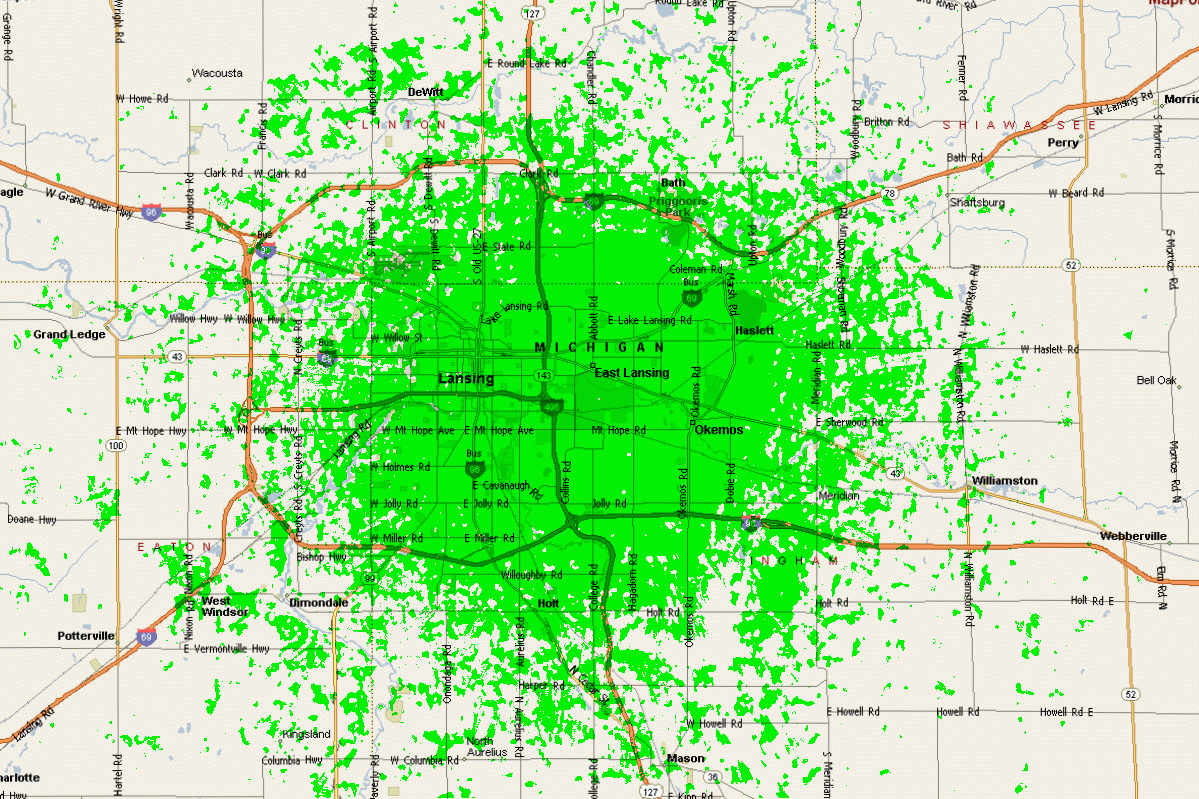
This plot depicts expected UHF two-way mobile radio coverage for a 440 MHz repeater after RF receiver system performance upgrades.
This coverage map was created using Radio Mobile Deluxe, a free-to-use coverage program.
440 MHz repeater coverage
The coverage standards used include:
Time 70%
Location 70%
Signal Quality ≥ Q3.5
Mobile TX 35 W
Mobile antenna: Standard gain mag-mount, roof center
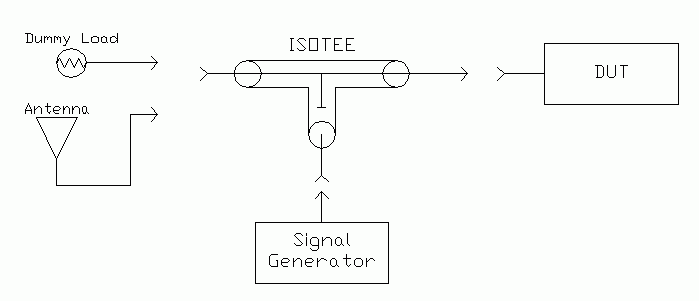
To detect the amount of “desense”, that is, how many dB receiver sensitivity is degraded when connected to the antenna from its own or other transmitters, and trace the desense source, a signal generator with an “isotee” is used to generate a precise signal level with a dummy load and antenna.
The test is accomplished in two parts–first determine sensitivity loss the system has by ambient antenna system noise.
connect the dummy load, then note the SINAD level achieved for a given signal level (typically values of 10 to 15 dB would be used).
the antenna system is connected, and the signal generator RF output level is raised until the SINAD reading matches that with the dummy load. The difference between the two signal generator level in dB represents the loss of sensitivity caused by ambient site noise.
the test is repeated, but this time transmitting while measuring SINAD (if the device under test is a repeater or full-duplex device). The increase in signal generator level over that required to overcome ambient noise is the amount of desense created by the transmitter.
It desense is observed with only the dummy load, assuming the dummy load and test cables present a good impedance and are well shielded, then suspect the duplexer is mistuned, or there is a cabling/connection problem.
If no desense with the dummy load, then proceed to test the antenna system.
If a rise on the antenna system only suspect bad connections or lightning protector that’s gone bad, or a bad antenna (cheap model or oxidized to create IM products).
Expected repeater dense measurements: ideally there would be no site noise (rather, site noise below the thermal noise floor set by cabling).
This is usually not the case, especially for VHF.
Expect to see some single digit dB degradation due to site noise on VHF, hopefully less than 3dB on UHF and above.
Isotee repeater desense connection
In terms of desense caused by the repeater, it should be below detectable levels.
Only in cases where the so-called “flat-pack” notch-only duplexers should there be detectable levels of desense from the duplexer.
With flat-packs it should be 1dB or less.
If using band-pass/band-reject duplexers with quality RG-142 cable and N-connectors, there should be no desense to the 100 Watt+ output level.
An examples 450 MHz repeater desense measurement was the repeater desensing itself 6-10dB.
The level varies and sometimes is up to 15dB.
This may indicate an antenna system issue, either alone or in conjunction with a duplexer/connection issue–but a more precise diagnosis would need to be undertaken first.
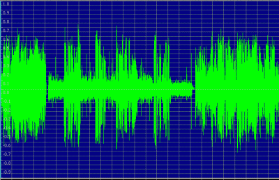
In this audio clip hear how it’s somewhat difficult to hear with TX on, then easy to hear with TX off, and hard again with TX on.
audio waveform from noisy RF transmission with static due to repeater desense
The following is a detailed example of how a radio system can suffer poor performance due to initial deployment or degradations, and how they can be fixed.
According to comments from repeater users in the primary coverage area, as well as Internet-connected VoIP radio users, the repeater system was not working satisfactorily.
Particular concerns (both noted beforehand and discovered while in work) were:
Audio dropouts on weak/fading RF signals.
Excessive squelch bursts after stations unkeyed
Audio quality of normal RF transmissions (quiet and unnatural tonality)
Excessively loud voice prompts from the repeater controller, so much so as to splatter adjacent channels due to clipped audio.
Excessively loud tones for CWID, DTMF cover, etc.
Bassy audio from the Internet
“Whining” noise on the audio from the Internet
Tinny (excessively high-pitched) audio to the Internet
Excessive voltage to the controller’s analog input from the repeater
Audio input and audio output between repeater & controller were ungrounded
Control signals between repeater & controller were ungrounded
A significant issue addressed in another report is the intermittent RF receive performance, where several dB change of
effective sensitivity
is noted occurring randomly (to the negative).
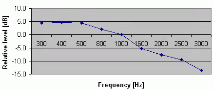
The audio performance was fixed to be nearly flat by modifying a repeater controller capacitor value. Here is the pre-modification audio–very bassy.
This is corrected to 0 dB at 1000 Hz.
The repeater had about +3dB gain at 1000 Hz.
Ideally, the passband would be a flat line at 0 dB—the data shown here is characteristic of a non-pre-emphasized transmission.
Normalized bassy repeater audio--should be flat
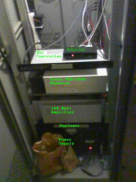
100 Watt UHF repeater system
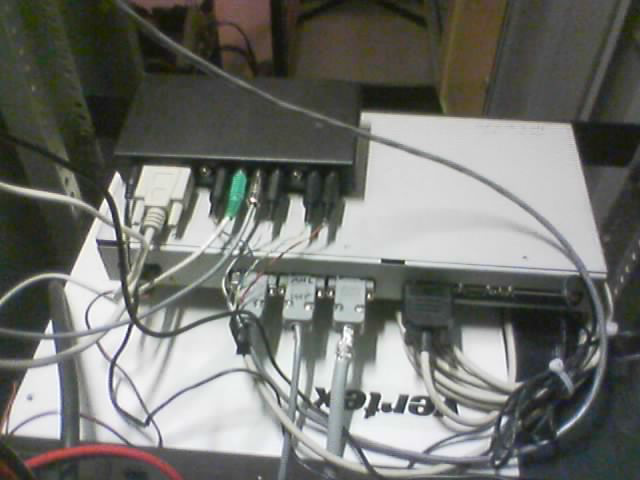
view of repeater backside
The repeater controller was programmed to switch channels on the repeater, in effect turning the PL transmit on and off at certain times.
One of these “off” times was during the “hang time” of the repeater, which is the period after a system user stops transmitting and before
the repeater stops transmitting.
This hang time is usually several seconds long to avoid excessive wear on the repeater, and to avoid
having to reinitialize PL detection on all the system receiving units for each transmission, which can cause the first word to be missed in a transmission.
The cause of the audio dropouts was narrowed down to the repeater not being able to handle fast, repetitive transitions in channel switching as occurred during weak and fading input RF signals.
Randomly, the transmitter would get stuck NOT transmitting PL during a user’s transmission, causing the repeater to stay transmitting, but the audio to be lost.
The channel changing output was thus disconnected to avoid this issue, and because PL disable is undesirable in radios systems from the 1970s onwards.
Some repeaters are not able to close the squelch quickly enough after non-reverse burst PL users have ceased transmitting.
This causes a “squelch burst” of noise to be heard after each transmission.
On this repeater system, this squelch burst was measured to be 50 to 150 milliseconds long.
This squelch burst can be completely removed with a digital delay module such as the RLC-ADM.
It was discovered that the RLC-ADM digital delay module was in the RLC controller, but was not connected to the COR line.
This caused the RLC-ADM to not function fully due to it “free-running,” not knowing where to start and stop passing audio.
Upon connecting the RLC-ADM to the COR line and increasing the storage time of the RLC-ADM, the RLC-ADM was observed to remove virtually all of the squelch burst, yielding less fatiguing operation for system users.
The audio passband of the repeater was checked using a digitally generated tone source as well as the repeater’s internal tone generator.
It was noted that the input/output ration was not 1:1, rather, a tone going into the repeater would come out at about 75% of original
strength. This caused users to have to talk louder or closer to the microphone than normal.
Also, users seemed to have “pinched” audio as compared to simplex operations—some loss of fidelity is inevitable when
operating through a repeater, but the audio seemed to have a notable dip in low and midrange, and a pronounced rise at high frequencies.
The cause of this was identified as ungrounded audio—the audio ground on the repeater was not connected at all.
This caused the impedance to be indeterminate, and the natural capacitance in the repeater and controller acted like a filter of unknown characteristics.
Once the audio was appropriately grounded to the proper pin on the repeater, and an additional ground was provided for control signaling, the audio
characteristics became more normal—BUT—now they appear to have the characteristics of a non-pre-emphasized repeater input—the repeater must be reconfigured for pre-emphasized audio.
The RLC controller had deemphasis disabled, possibly to help the previously distorted audio, but it must have deemphasis enabled since all end users will have preemphasized audio.
Now that everything else is to normal, the repeater was reconfigured to accept normal audio.
The Voice Prompt level was noted to be at about 4 times the level called
for in the controller manual. The level was reduced by 75%, to about
2kHz as called for in the controller manual. This caused the voice
prompt to be at a natural level and to not splatter adjacent channels.
The Tone level was at about 3 times the level called for in the RLC controller manual, so the level was reduced by about 65% to 1.5kHz as called for in the RLC controller manual.
This caused the tones to be at a more natural level and not disturbingly loud.
Also, because the RLC-ADM was now properly connected, the DTMF cover tones could be disabled since the RLC-ADM mutes the tones.
The cause of the very bassy audio from Internet was due to the ungrounded audio as noted in item 3.
Once the ground was appropriately connected, the audio was normal except for the cause listed in item 3 that must still be resolved.
The whining noise came from a ground loop caused by not having a proper separate control and audio ground—the PA fan noise was being modulated.
Once the repeater grounds were connected as noted in item 3, and the levels were realigned, the whining audio problem was resolved entirely.
The tinny audio to the Internet was because the RLC controller has deemphasis disabled.
Now that deemphasis is enabled as noted in item 3, the audio is normal to the Internet.
The VXR-5000 repeater provides an analog voltage relative to received RF signal strength from about 1 to 6 Volts DC.
This level exceeds the 5 Volt maximum analog input of the RLC controller.
Because this function was not configured, the quickest resolve was simply to disconnect this input until a proper voltage divider would be constructed if this feature is desired at some future date.
Control signals between repeater & controller were ungrounded.
These issues were unexpectedly discovered while tracing the source of previously mentioned audio problems.
The audio and control seemed to be finding their returns through a connection on the Analog input connection for control, analog sensing, and audio functions—obviously an undesirable situation, causing previously noted audio issues.
Two ground connections were added for audio and control, which had previously been ungrounded.
This resolved the audio issues noted previously and allowed the inputs and outputs to be disconnected due to previously noted undesirable characteristics.
The original plan of using a surface mount toroidal splitter was dashed when the one unit obtained was defective.
Rather than deal with another wait to get another, and for the challenge, we decided to construct a Wilkinson power divider.
We first used a set of approximation functions from Bahl’s A Designer’s Guide to Microstrip Line, in Microwaves, May 1977.
They worked fine for the initial microstrip design, but for a confidence check we ran another set of piece-wise approximations obtained from Gupta’s Microstrip Lines and Slotlines.