No practical two-way wireless system has infinite subscriber capacity in finite time.
For commercial and public safety systems from analog LTR, Multinet, and Passport trunking up through APCO-25, DMR, NXDN or iDEN trunking there is channel access latency.
PTT latency, that is, the time it takes from the user pressing the PTT switch to getting the “clear to talk” tones is a key source of frustration on a trunking system.
Trunked PTT latency is not the same as conventional (non-trunked) users are accustomed to.
They must be considered when designing public safety and utility systems and training their end users where safety of life is as stake.
There are parallels to these problems in conventional systems particularly during adverse events.
We give a qualitative overview of the issues in this article.
These issues apply equally to trunked radio systems on any of the common two-way radio bands.
In the United States the most popular bands are VHF (150MHz), UHF (450MHz), 700MHz, 800MHz and 900MHz.
Other countries have other frequency bands popular for two-way radio.
A lot happens in the fraction of a second between when a user “keys up” to talk and the clear to talk being issues.
Consider this in the light of trunked radio technology being nearly four decades old.
Motorola chose to go with a 3600 baud FSK control channel.
The downside is that channel cannot be used for voice at all, but the PTT latency is significantly lower and the contention behavior (two users trying to PTT at same time) is vastly better than for LTR systems.
Motorola Type I and II systems use a single sine wave “connect tone”, which is like a CTCSS code, but one that is used across the system.
Connect tone is analogous to:
SAT tone in AMPS
Color Code in Passport
Area Code in LTR
System Key in Multinet
A brief burst of disconnect tone avoids tail bursts of noise.
The repeater transmits to the subscribers a subaudible 150 baud “OSW” during voice transmissions, subaudible data of increasing complexity with newer Motorola trunked systems.
This is necessary to allow priority override of transmissions (“calling all cars”) and other advanced signaling.
A key advantage of Motorola trunking (and all other trunking except LTR) is that individual subscriber radios can be individually disabled on a repeater.
This helps ensure that all radios used are paying the monthly per-radio rate.
For public safety and other systems, lost radios can be disabled “stunned”.
Clearchannel LTR uses a 300 baud FSK subaudible signaling, so that voice and data flow on any channel in the system.
A consequence of the higher baud rate than DPL or Motorola OSW is that LTR has a more audible background noise, that some users have compared to a diesel truck idling.
Passport likewise has higher “wub wub wub” digital subaudible interference in the audio.
Without custom programming on the radios, the LTR subscribers have to request a channel each time, there is no “memory” of the last used channel without custom repeater controller software.
This means the relatively fragile and lengthy LTR channel request is repeated each and every PTT.
As long as a radio is listening on its home channel, priority override transmissions (from a priority talkgroup) can occur.
If a user has trunked away from the home channel, priority override won’t work until the transmission ends.
Custom repeater software (MultiNet) could drop non-priority calls (cease transmitting) to force users back to home.
Passport systems have optional ESN validation, which occurs upon turn-on
(or as soon as the radio gets in range of a system).
Keying up on a Passport system takes just a bit longer as the MIN is transmitted along
with the desired talkgroup.
From slowest to fastest keying in the discussed systems are: Passport, MultiNet,
LTR-Net,
ESAS, LTR, Motorola Type II/I.
LTR-Net, ESAS and the constriction of two-way radio:
Despite some eye-popping investments including by those turning their Nextel-bought SMR back into trunked radio, I don’t hear about these system anymore.
With the most widespread first generation trunked system (LTR), there was a pent up need with no alternatives.
That is, the wireless two-way dispatch choices through the early 1990s were:
conventional (PL/DPL)
trunked (LTR, Motorola Type II/I, MARC/EDACS)
analog/digital cellular
Conventional and trunked two-way radio were offered at monthly prices of $15-$25/radio depending on system coverage, competition, etc. with effectively unlimited minutes typically.
Cellular by the mid-1990s was settling down to roughly $100/month for light to moderate business users.
Two-way radios had a payback time of easily a year or less through the mid-1990s.
Then the digital cell phone resolution hit, allowing several digital phone conversations to fit in the space of one analog cell phone conversation.
PCS and other spectrum auctions of the mid to late 1990s brought a multiplication of spectrum available for voice and soon more and more data with the mobile internet coming at the millennium turn.
The goal of the cellular carriers was to push ARPU higher and higher naturally, from $60 to $80 a month.
Texting suddenly became something to charge $10/month for.
So one could argue that business cell phone monthly prices had stopped falling drastically by about 1995, and more slowly went up and down depending on what addons corporations wanted.
What brought the constriction of traditional two-way radio shop business models in the early 2000s was a confluence of factors including:
highly-reliable, stable radio circuitry lasting 5 years between repairs, mainly to physical wear
#1 hastened the attrition of an aging workforce, where companies like Bearcom and many others offered flat-rate repair, with their business model allowing whole-board replacements on the backs of other radios fixed cheaply
Psycho-social: as cell phones trickled throughout white-collar to grey-collar, the site managers started “forgetting” to turn their radio on, or “not hearing” calls through an “intermittent” radio. Once those excuses worked for the foreman, the rank-and-file started using them. After a few years, they all had cell phones and $100 worksite simplex walkie talkies.
The high-margin two-way radio business that remains includes
industrial customers that pay someone to handle their problems, that don’t want to assign someone to ship/receive radios to Bearcom. They appreciate quick fixes.
medical customers that need help getting radio systems to work throughout their dense and expanding campuses. No Wifi radios yet.
educational physical plant and security; similar to medical they have big and growing campuses. Cell phones don’t always work in the basements they need to ply.
City/county utilities and services: a long mainstay of radio. Just too many radios to replace with cell phones, their accountants wouldn’t like it given great ROI of self-owned two-way radio systems.
the obvious public safety and critical infrastructure that are mainstays for at least another decade.
You will notice the issue–the five categories of high-margin customers remaining in two-way radio ALL run their OWN radio system.
The long tail of commercial users dried up considerably over the past decade.
Of course, there are still farmers, taxis, construction and other vertical markets.
Looking at each of them in turn:
farmers: highly seasonal use patterns. Local cell companies accommodate with seasonal turn on/off of phones. Low minutes used
taxis: quick blip of Nextel Direct connect gives pickup address. Less than minute call upon passenger pickup. Company margin high, demand growing, coverage area expanding. Not a dead two-way radio market, but shriveling
construction: Cheap jobsite repeaters and cheap two-channel radios are all most need. Even the average joe has a cell phone now, after a few months their foreman gets the number.
and so on.
As service companies (and every other company type) consolidated in the early 2000s, their workers covered larger areas, outside even the reach of a single two-way radio provider’s repeater network in too many cases.
Thus, even the first-generation commercial trunked network systems like LTR-Net (1999) and ESAS (1996) came too late, they effectively came post dot-com.
A key distinction with Trident Microsystems Passport is they came at it from the Motorola angle, going for a higher-end market (actually mid-tier).
Now in 2005, the bulk of the two-way radio business is split from low to high tiers:
conventional repeater users: small construction companies, other small users that are too big to switch to cellular but small enough in number and usage to bother switching to trunked (yet). They are profitable even if the old repeater has to be replaced with a trunking/conventional repeater.
trunked LTR users: coming off of SMR, these are the bread and butter. Still good for $20/month/radio
networked Passport users: for those taking on the risk, can you charge them extra for the infrastructure costs or will they just go cellular
self-owned users: one-time profit + maintenance
The April 2005 announcement of digital NXDN at IWCE may slow big investments in Passport.
Another big manufacturer is said to have commercial digital radio in the works to compete with NXDN.
Physical and Engineering Causes of Trunked Radio System PTT Latency:
Four causes of PTT latency in analog and digital trunked systems are:
Poor SNR (subscriber → tower or tower → subscriber)
System overloading (all channels busy or too many suddenly try to transmit)
Malfunctioning radio/tower radio
Poor RF design or interference (radio or system)
Let us examine these in turn. In Part 2, we will do quantitative
simulations of each failure type.
Wireless communications, particularly of the NLOS variety experienced in typical two-way radio is characterized by deep fading.
The frequency of the fading is influenced by wavelength, hence why 800MHz and 900MHz sound so much more “fluttery” in analog systems vs. 150/450MHz.
Digital radios use signaling designed to statistically fight fluttering, and so effective system coverage quality for a given DAQ can be much larger, tens of percent larger.
Distinct techniques are employed by radios and repeaters to handle the errors in the subaudible data, which has led to lawsuits over
copyright issues.
With the long PTT cycle time of LTR, there is a real chance of two users keying at the same time, effectively jamming each other until one or the other gives up. On systems where too many users are on one home channel, this becomes more problematic and even an ongoing problem.
If a radio is off frequency, or a repeater modulation balance is misaligned, this can lead to significant digital bit error rates, and intermittent performance at any signal level. [to be continued]
In any trunked system, control/home channel performance is precious.
Multinet and Passport work around some of this by breaking up home/control channel functionality into two or three channel all the time.
Nextel interference, co-channel interference, adjacent channel interference can pop up unexpectedly.
We provide assistance in evaluating whole-system performance.
Sometime simple fixes implemented on a first site visit can improve your radio system performance.
Why the gaps right at the most useful frequencies?
Because of
FCC R&O 99-58,
38 dB of rejection for 12 dB SINAD signal in the Cellular Block A and Block B bands.
This was an update to
FCC ET Docket 93-1
establishing the obligation of OEMs to block Cellular Radio Service (824-849, 869-894 MHz) reception after some eavesdropping scandals of analog FM (AMPS) cell phones.
OEMs may block image frequencies such as the 902-928 MHz band that would be very useful for amateur radio operators to receive on.
The Yaesu VX-7 has a fourth-order varactor-tuned bandpass filter comprised of HVC355B varactor diodes (D1015 and D1017) with parallel inductor tank circuit for each section of the filter.
The IF frequency is 47.25 MHz, and Yaesu is blocking the first and second image frequencies, hinting that the Q of the filter is low–very broadband.
IF image matrix vis Yaesu’s frequency blocking strategy:
824-2*47.25-0.45=729.05 MHz ← right where Yaesu starts blocking frequencies.
849-2*47.25-0.45=754.05 MHz ← OK, that’s blocked, but they wait until 758 MHz to start allowing reception. Design fluke?
869-2*47.25-0.45=774.05 ← they start blocking again
894-247.25-0.45=779.05, 849-47.25+2 0.45=802.65 ← rounded up to 803 MHz?
869+47.25-2*0.45=915.35 ← rounding down to 915 MHz?
849+2*47.25+0.45=943.95
869+247.25-2 0.45=962.4 ← rounding down to 960 MHz?
894+2*47.25+0.45=988.95
So that means it’s the first image that’s an issue–isn’t that what the tunable bandpass filter in the first IF is supposed to be for?
Usually we expect 50-70 dB image rejection.
Clearly that’s not the case here, hence the frequency gaps.
12.5 kHz channel compatibility: the VX-7 has filters only for 25 kHz channels.
This means the VX-7 is more subject to adjacent channel interference when in a 12.5 kHz system.
The transmit deviation can be reduced for 12.5 kHz channels.
In contrast, the mobile radio Yaesu FT-8800R has switchable 12.5 kHz and 25 kHz filters for each of the main and sub receivers.
Split PL/DPL tone: the VX-7 can only do a mix of PL/DPL split, you can’t do distinct TX/RX analog PL tones.
Some repeaters with high altitude and/or voting receivers use DPL on the repeater receiver input, and transmit with analog PL.
This is sensible because repeaters are targeted toward mobiles and portables, and maybe base stations with directional antennas and low power.
Both in the commercial and amateur world, base stations with high power omnidirectional transmissions clog up distant repeaters, particularly at VHF where tropospheric ducting is more common.
Why not use DPL for both transmit and receive?
Because DPL has worse decode sensitivity than analog PL, particularly for low-quality decoders.
The repeater will have a high-quality DPL decoder, and the mobile is unlikely to hear the distant repeater, so analog PL receive is good for the mobiles, why give a double SNR decode penalty with DPL TX/RX.
For a system targeting wide geographic coverage, two alternating repeater RF output frequencies might be used, and keep the same PL for simplicity.
The systems can be linked via RF or VoIP backhaul, and the end user selects which repeater receives them by switch mobile transmit PL.
If the systems are unlinked, interference is avoided since everyone hears the overlapping repeaters.
This is something the VX-7 cannot do, without using PL on transmit and CSQ receive.
Modern cars and environments have a lot of RF noise from computers and communications.
Carrier squelch will breakthrough not infrequently on nuisance interference.
Repeater should transmit coded squelch so users can filter out background RF noise.
The RX sensitivity specifications are easily met.
We hear airplanes a couple hundred km away on VHF AM airband (108-136 MHz).
Sirius XM receivers began wide availability factory-installed in automobiles in the early 2000s.
Both Sirius and XM use left-hand circular polarization (LHCP).
The authorizations allow future flexibility to use RHCP to get polarization diversity multiplexing, which could someday increase throughput within the limits of cross-polarization performance of end user antennas.
XM Radio reception is possible inside a metal structure (walls and ceiling) where we were unlikely to be within range of a terrestrial repeater.
The key factor to XM Radio reception indoors from the vehicle was that the metal garage door nearest the vehicle were open and south-facing.
Lets examine the SDARS link budget.
SDARS XM/Sirius Radio link budget:
While XM uses a significantly more sophisticated modulation and interleaving scheme than Sirius, for simplicity let’s use Sirius’ simpler 4.5 MHz QPSK single stream as the model since it will perform worse than XM in general.
That is, a single QPSK stream at 4.5 MHz RF bandwidth will get a Sirius radio to play music.
EIRP satellite ~ 90 dBm (1 MW)
Thermal Noise power in 4.5 MHz BW: -107.4 dBm
Elevation angle: 30 degrees (roughly based on latitude ~ 49 degrees ~ worst azimuth)
Path loss to geosync at 2.345 GHz ~ 192 dB
Rain loss ~ negligible
Sirius/XM Radio link margin [dB] = 90 - 192 -(-107.4) ~ 5.4 dB
This is within reason for 10-4 BER with QPSK and Reed-Solomon.
While I would assume the highly simplified calculation above neglects a few dB (is too conservative) this shows it’s within the realm of reason, and that a big unfurling antenna on the satellite is important for more gain.
Spatiotemporal diversity is a very important factor, yielding ~ 10 dB of effective gain under many scenarios.
Foliage drains back another few dB statistically.
Basically, it’s give and take, and it seems likely a great amount of effort was spent modeling and measuring.
XM Radio FCC Authorization cost $90 million in its winning bid, FCC DA 97-2210 authorization order coming in October 1997.
The frequencies from 2332.5-2345 MHz were authorized for XM Radio broadcast of various services including voice and music subscriptions.
Late in 2001, XM Radio finally became publicly available using two geostationary satellites: “Roll” at 85 West and “Rock” at 115 West using LHCP S-band antennas.
The terrestrial repeaters use vertical polarization, which is received with 3 dB loss by the LHCP end user antennas as implicit in linear vs. circularly polarization antennas in the same system.
XM Radio Technical characteristics:
March 2001
FCC Order DA 01-699
increased XM Radio EIRP from 62 dBW to 68.5 dBW (that is, from 1.6 MW to 7.1 MW).
The frequency authorization consists of four 1.84 MHz space-to-earth channels and two terrestrial repeater channels each of 2.53 MHz.
The center frequencies are:
Roll: 2333.465 MHz, 2344.045 MHz
Rock: 2335.305 MHz, 2342.205 MHz
Terrestrial: 2337.490 MHz, 2340.020 MHz
XM Satellites are bent-pipe transponders from X-band to S-band, like Sirius.
FCC Order DA 01-2172
on Sept. 17, 2001 gave an STA (Special Temporary Authority) for the long-anticipated terrestrial SDARS repeaters, ultimately necessary even for the elliptical Sirius orbit and much more so for the geostationary XM orbit (parked over the equator).
This STA gave the OK for 180 days of 2 kW EIRP repeaters in general and specifically listed > 2 kW EIRP repeaters.
The repeaters had to be the whole channel set completely matching the satellite broadcast–working to stave off fears of custom local terrestrial channels only on the repeaters for a particular city.
May 18, 1990 was in a way the initial firm public step towards US mobile satellite radio with Sirius FCC application.
October 1997 Sirius was initially authorized in
FCC Order DA 97-2191
for the 2320-2332.5 MHz band using LHCP (left hand circular polarization), for which it paid $83M the same calendar year.
7025-7075 MHz was authorized for co-primary uplink for SDARS.
Service was planned to launch in late 1999 for the “lower 48” USA.
Initially Sirius planned to have two geostationary satellites – before launch, altered to be elliptical “tundra” orbits.
The Sirius service was initially planned to have:
thirty 128 kbps channels “CD quality”
twenty 32 kbps channels “FM quality” for voice programming
option to divide these channels as much as needed for auxiliary non-voice service
Of course what happened was that these channels were sliced even more finely to get the ~100 channels.
The digital compression artifact are readily apparent on Sirius as well as XM.
However, to most users they prefer dropouts vs. changing the radio station frequently or the pops and fizz of VHF WBFM multipath and fading combined with the high SNR requirement for FM stereo, and receivers that wait till SNR is too low to revert to monaural reception.
Terrestrial repeater authorization was explicitly deferred for a future authorization.
Early in 2002, Sirius finally became publicly available after years of wrangling with diverse and even humorous opposition reaching FCC filings over 12 years.
Distinctive from XM Radio receivers’ six simultaneous RF broadcast streams (two from each satellite, and two terrestrial), Sirius receivers use three streams (one from each of two active satellites) and one terrestrial.
Sirius receivers (end user) have three channel simultaneous receivers for time and spatial diversity (simultaneous tuning of two satellites and one terrestrial repeater).
Sirius rotates which two satellites are active as the three (FM1,FM2,FM3) Sirius satellites pass over North America for best coverage of CONUS.
Each of the two Sirius satellite channels are 4.5 MHz using QPSK modulation.
Each channel is a copy of the other, with a 4 second time delay for time diversity (e.g. overpass, tree cluster).
The net Sirius satellite data throughout is 4.4 Mbps all-inclusive – voice, music, data, telemetry.
Each Sirius satellite is a bent-pipe transponder from X-band to S-band, and the downlink channel is selectable in case of needing to swap out for a bad satellite.
The single Sirius terrestrial repeater channel is also 4.5 MHz, but uses a different modulation scheme.
July 2000
joint FCC-State Dept announced
that agreement had been reached with Mexico for SDARS frequency bands, including terrestrial repeaters that had already been agreed to by Canada and the USA.
The specific terrestrial SDARS repeater frequencies were:
XM Radio: 2336.225-2341.285 MHz
Sirius: 2324.3-2328.3 MHz
Reference: Elbert, Bruce R. The Satellite Communication Applications Handbook. Artech House Space Applications Series. 2nd Ed. (2003).
For sound card amateur radio modes a simple SoundBlaster USB soundcard as the ADC & DAC on the built-in sound card didn’t have adequate SNR.
With the Icom IC-725, PSK31 works quite well on the USB sound card–since I don’t want to splash 3 kHz at 10 mW of internal soundcard hash on the air.
On CB 27 MHz it’s hard to talk to base stations 25 km away during the day–a striking difference from a few years ago when the sun was quiet.
But this means a boon of DX on ham frequencies.
Radio Coverage Map verification and range test of such radios is as follows: put the base station into VOX mode, and setup the PC to play a tone N seconds long every M seconds.
Then, setup the PC to simultaneously record continuously (or use a separate recorder).
Now you have a timed radio coverage system–synchronize your watch and PC clock.
Then, even for the maximum range case where your base will hear the mobile but not be able to understand it, because you record your location vs. time in the car, based on the number of beeps you can match unreadable transmissions with where you were–which is often more important than where you can hear!
Public safety is ensconced below 860 MHz while Nextel blasts away with wideband CDMA above 862 MHz.
A police station was missing every fifth or so radio transmission.
This immediately raised some ideas, since the trunking system was 5 channel, of the type that used a low-speed subaudible data control channel shared with voice.
While transmissions that worked were heard crystal clear, due to the quieting effect of FM, we know that there is a rather non-linear relationship between C/N and SNR.
That is, the FM improvement factor once you’re over the signal level where popping and cracking stops puts you quickly to the 35dB maximum SNR typical of FM communication radios.
The link could be weak but you’ll only intermittently see problems.
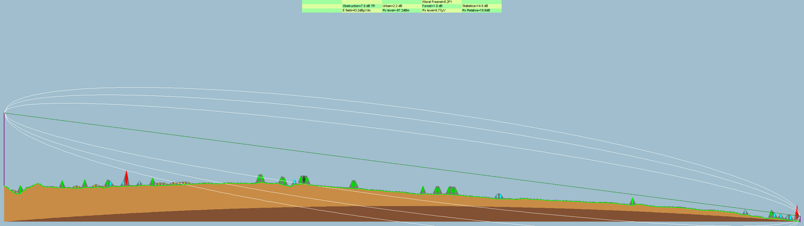
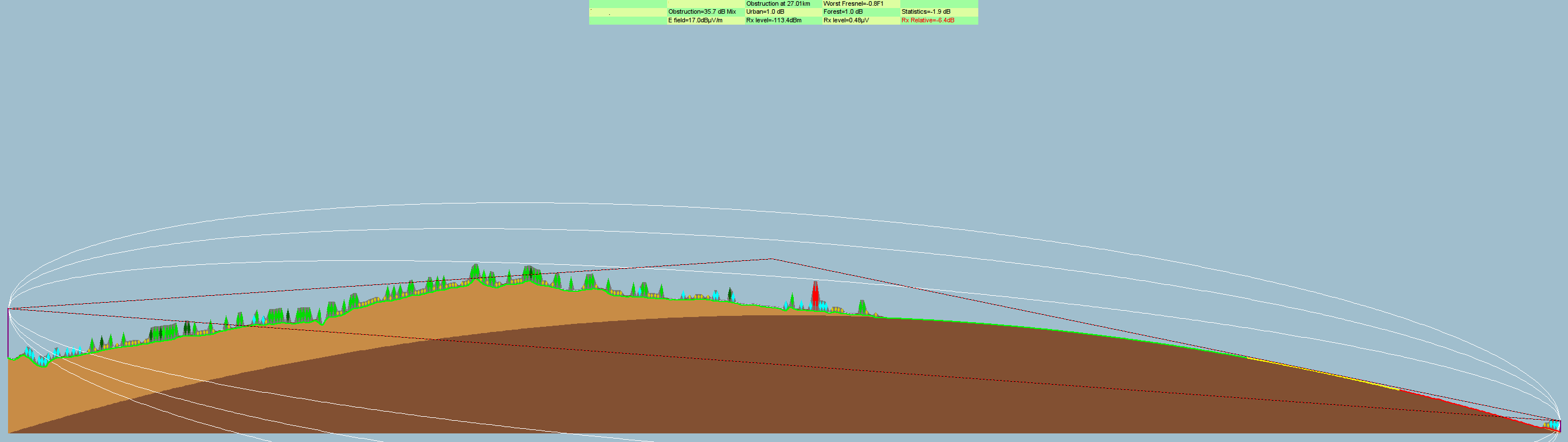
We used
Radio Mobile Deluxe
for a “radio link” path simulation as seen at the top of this article.
The over 40 km path length despite the mild terrain leads to only 0.2 Fresnel zone clearance instead of the desired ≥ 0.6.
Since this system had only one central transmitter for the county, and the police station antenna was on a tower with a good gain omni antenna, there wasn’t much to do.
The omni antenna had to stay to allow for backup simplex (radio to radio) communications in case the main tower went down–they weren’t going to buy a second base radio or swap yagi to omni antennas in that
case.
Radio Path profile
The deficient design of the county-wide 800MHz system caused a variety of problems due to having the single central transmitter on a tall hill and a very tall tower.
You just can’t be 40 km from a transmitter and get a solid signal when safety of life transmissions are concerned.
Yes, ham radio operators go over twice that distance on VHF/UHF repeaters, but two key distinctions are:
Ham repeater frequencies are generally afforded far more co-channel and adjacent channel protection than commercial frequencies
Ham radio operators will tolerate far more static, fading, repeating transmissions than police officers in hot pursuit
In fact, given terrain in other parts of the county, some places only 20 km from the tower had problems with reception.
Yes, there was a receiver voting system, but in a trunking system, you have to hear the base station before you can initiate voice communications!
You can’t say “man down” on a trunked system even next to the voting receiver if you can’t hear the base transmitter.
Exception is for the emergency button, the protocol designers were smart enough to allow the emergency unit ID to go through even one-way.
We set a conventional receiver to each of the channels and listened for the 10-second periodic “kerchunk” of each repeater.
We noticed the repeaters were roughly the same signal strength by ear.
No other complaints had come in besides the usual.
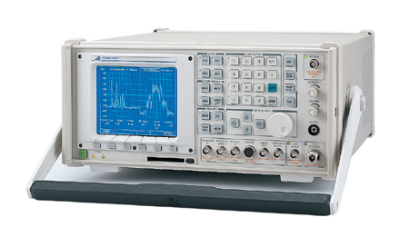
We did a few test transmissions at the police station from their radio, tested their radio with an Aeroflex COM-120C service monitor, checked the SWR with a Bird 43 wattmeter, all was well.
Aeroflex COM-120C service monitor. Photo copyright Test Equipment Connection
The spectrum analyzer showed the 5 repeater channels were approximately equal in strength, allowing for fading and instrument accuracy.
The received signal amplitude was in line with the path loss predictions, keeping in mind the confidence interval in the Longley-Rice propagation model.
We reprogrammed the police base station to listen directly to each of the channels.
We noticed a clear SNR deficiency on only one channel, despite the spectrum analyzer showing nearly equal signal strengths and equal background noise level within the sensitivity of the spectrum analyzer.
The spectrum analyzer intrinsic noise floor was on the order of -100dBm for the resolution bandwidth.
Spectrum analyzer resolution bandwidth trades resolution for update rate.
Large resolution bandwidth gives very rounded-off traces at decent update times.
Small resolution bandwidth gives fine traces at slow update times.
Nextel’s iDEN signals fill the channel with a fairly uniform spectrum.
You can’t zero in on a carrier like you can with analog transmissions and wait for the analyzer to update.
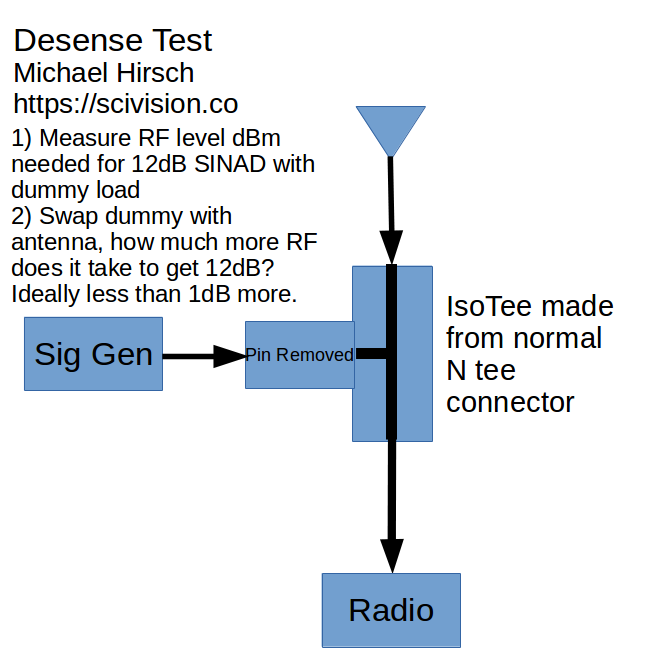
The “desense” test uses a special T-connector called an isotee that passed straight through between antenna and radio, and the T port had the center pin removed.
The isotee provides controlled (at least at each frequency) isolation such that a signal generator connects to the isolated port, and the radio is connected to the antenna via the other two ports.
isotee diagram for desense check
Four channels were normal, perhaps less than a dB desense.
The fifth channel had perhaps 10-20 dB of degradation, fluttery time-varying.
Changing the signal generator frequency slightly did not generate beat notes.
Tuning the radio/sig gen to one 25kHz channel either side didn’t have the interference.
The interference was fluttery but constant otherwise, no duty cycle.
Nextel despite purchasing up SMR licenses in those days did not put sites at the license coordinates necessarily.
They took advantage of the SMR regulation allowing different site location as long as the license footprint was not exceeded.
This is where the cell phone DXing came in.
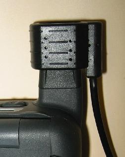
We used a Wilson antenna adapter on a Nextel i850.
Dialing # , * , Menu, Right to go into field test mode, gave current frequency and signal strength in dBm, among other parameters.
Wilson Antenna coupler slid over Motorola i850 antenna, allowing use of external antenna for far greater range (photo copyright Wilson Antenna)
There was not cell service locally available at ground level.
With an external antenna the Nextel signal was there.
he Nextel phone showing similar signal strength on the Nextel signal as what the non-directly observable interference might be.
Nextel field engineering staff were a bit surprised that a Nextel tower over 90 km away could be a bother to a police radio.
We noted the weak desired signal, and the part of the interference path that went over water.
This configuration was conducive to thermal inversion layers.
Superrefraction can make radio waves travel unexpectedly long distances.
He put in a channel change request.
The desense test then showed all repeater channels were good.
Hopefully someone at Nextel did a license search to give a wider co-channel geographic exclusion zone for public safety licensees.
It would be a simple FCC license search away.
SCADA systems from Mitsubishi Alpha to MOSCAD can use wireless networks such as MDS microwave relays.
Critical infrastructure systems own radio networks help maintain control in the face of a major telecom failure.
Leased lines are too expensive, POTS dialup can be fidgety.
Municipalities and utilities small to large can’t afford to rely on weak communications command and control linkages.
Old systems based on DTMF or proprietary signaling systems can be replaced with MOSCAD or the like having timestamped, encrypted anti-playback capability.
No factory-default passwords, make the SCADA equipment require a sufficiently sophisticated password.
Find ways to make certificates and other “beyond password” measures a reality with embedded critical control systems.
Sometimes adding just 2% percent to a system cost adds 15% more value.
For example, using narrowband data to pumps and broadband data to substations can reduce antenna needs for the narrowband stations, allowing increased robustness in remote areas.
Triggered camera recording with periodic snapshotting allows identification of malfeasants over a modest data pipeline vs. thousands of hours of unwatched video.
Instead have high speed video when the installation is approached.
These approaches exploit the latest in encrypted, license-free data radio technology, allowing rapid upgrades without dealing with contentious cross-border licensing issues.
The higher directivity of 900MHz yagis vs. VHF yagis allows denser networks and less interference from tropospheric ducting a.k.a. “skip” from hundreds of miles away.
Multipoint operation reduces the need for a tall central tower(s)–or have multiple supernode locations with more modest elevation.
A particular entity used two-tone paging for life-critical voice paging across a county-wide area.
They wanted a backup paging system that could work in a standalone fashion without any other infrastructure.
In case of a major system/telecom failure, they could still send coded one-way broadcasts to key agencies.
They had been sold a system using a mobile two-way radio in a suitcase with antenna, which transmitted to other two-way radios tied into each paging base station to control the powerful paging transmitter.
After a cursory examination I could immediately see why this system worked poorly under real life conditions.
Part 1 of this case study details qualitatively what was wrong, and Part 2 will look at simulation in GNU Radio.
good remote two-tone paging link design
Old, undesired remote 2-tone paging
Every connection on the diagram except the antennas is wrong.
I gathered up all the items except the paging transmitter back to the office.
Let’s go from right to left in the diagram above, exploring what needs improvement.
They needed to use speaker audio to get enough amplitude to go into the 600 ohm line input of the transmitter.
They used a resistive voltage divider where an 8 Ω resistor was connected across the speaker output, and each side of that 8 ohm resistor went through something like a 1000 Ohm resistor to each side of the line transformer.
This was not impedance matched and so the frequency response of the main line connection as well as the paging backup was distorted.
The volume control affected the paging levels from the backup.
The carrier squelch receiving CM200 would hear all signals on the UHF frequency.
The only thing stopping anyone from blasting out messages across the whole county was the fact that no one else sent tone remote controls across the air.
The non-flat audio meant with the 2175 Hz and 1950 Hz control tone levels OK, the low frequency two-tone paging would be too low.
Don’t send sensitive control tones across the air, the dynamic range of a radio channel isn’t wide enough and the interference rejection (capture ratio) isn’t high enough with the insufficient dynamic range
Don’t do critical functions across a carrier squelch link!
Don’t use non-flat audio for links, it’s hard enough to get the levels right with flat audio
The transmit CM200 at least complimented the settings of the receive CM200: carrier squelch, preemphasized audio.
We would reprogram this radio to suit a more stable, secure system in the next section of this case study.
The Zetron tone remote was hacked to add a PTT relay and cutting down the audio level to feed a microphone input on the CM200.
This should have been left factory, and use a tone remote interface on the transmitting CM200.
The engineering issues starting with the most severe included the following.
Sending level sensitive tones over a link with insufficient SNR.
The SNR of a narrowband commercial radio is about 35-40 dB.
The dynamic range of the control tones is 30dB, as follows.
+10 dBm 2175 Hz
0 dBm 1950 Hz
-20 dBm 2175 Hz for the duration of the transmission.
A POTS line has SNR in the 35 dB range for a good signal, limited by the ADC/DAC PCM conversion and hardware.
Apparent SNR seemingly higher than 35-37 dB is observed by compressing the audio, but a careful test will show the actual instantaneous SNR when PCM is involved as in any modern POTS line won’t be higher.
So why didn’t the radio link with 35dB max SNR work when the POTS line at 35dB max SNR works all over 24/7/365?
The POTS line does not experience nearly the same impairments that a typical radio channel does.
The tone remotes are designed to withstand oddities of POTS behavior, NOT radio link behavior.
Consider the deviation level if we put the +10dBm 2175 Hz tone to have 70% modulation, that is, ± 1.75 kHz deviation in a 12.5 kHz bandwidth (± 2.5 kHz max deviation) system (the current FCC standard for commercial two-way analog FM).
We don’t want to go any higher than that because the deviation limiter of the radio starts to kick in, making the tones non-linear.
Then the other tones will have deviation as in the following table.
Tone level (dBm @ 600 Ω)
Deviation (± kHz)
Tone freq (Hz)
+10
1.75
2175
0
0.55
1950
-20
0.032
2175
The last row of should set alarm bells off.
32 Hz of deviation is an extremely low level, a level of perturbation that easily comes about from noise and interference.
Beat notes from another FM transmitter on the same channel can create energy in bins near the 2175Hz guard tone that false the decoder and cause the paging system to stop transmitting.
Part 2 will show a simulation of this effect; it’s immediately apparent.
On modern POTS lines crosstalk and beat frequencies aren’t such an issue anymore.
The tone remote systems weren’t designed to tolerate this.
Using a carrier squelch system for a critical system backbone function is very inappropriate.
Use some type of signaling qualification at least as secure as other elements of the system, even if it is security through obscurity.
Sending non-flat audio over backhaul is troublesome with level-sensitive signaling.
It makes low frequency paging tones have low SNR, which is then repeated out the paging transmitter as a degraded signal, causing poor coverage for jurisdictions using low audio frequency two-tone pages.
Preemph/deemph is to help fading radio channels have less of a hissing sound, it’s not beneficial for what should be relatively strong signal links.
It doesn’t help co-channel interference.
The impedance matching problem was not helping frequency response of two-tone paging either.
For each problem noted in the last section:
Use standard radio signaling techniques (simultaneous subaudible modulation, tone burst at start of transmission) to act as the authentication.
This was no worse than what the rest of the system used.
The risk of intercept was small, and if an adversary had the equipment to get the radio codes, they could have simply gotten the radio codes for the rest of the system with less effort.
This meant that there would no longer be tone remote 2175, 1950, 1850 Hz signaling going on over the air, and the two-tone paging would be set for 66% modulation (+/- 1.65 kHz deviation) allowing maximizing SNDR (noise + distortion).
This was enabled by using a Vega DSP-223 tone remote panel between the Zetron and the CM200 radio.
This solution ties in with number one, +/- 300Hz deviation subaudible digital signaling was used continuously during the transmission, along with a brief ANI burst of +/- 1.5kHz. An ANI validation module managed this qualification on the receiving end. The system will work without ANI, it will just be less secure against others keying up the system.
It was easy to reconfigure the system to use flat audio, it’s just a programming selection and use of appropriate 16-pin connector pins.
Since the paging transmitter had a second local PTT & audio connection, we didn’t connect to the 600 ohm line used by the main consoles. We used an audio transformer to isolate the radio from the paging transmitter, and the signaling decoder provided a relay output to key the paging transmitter. The two-tones were sent from the Zetron after a delay long enough to allow for link receiver decoding (subaudible + ANI + paging transmitter keyup).
Part 2 will explore the quantitative radio link vs. POTS.
A VHF (150 MHz range) police/fire radio system was suddenly suffering from intermittently poor signal from a part of their coverage area, being noticably worse with rainy weather.
On VHF, receiver voter systems are more common due to the much poorer portable (handheld) radio performance versus UHF and 800/900 MHz systems.
We first checked the voter sites nearest the complaints including the line levels at the main repeater/voter.
If voter levels are incorrect, the voter can see this receiver as having poor SNR and always pick other receivers.
The remote voter receiver levels at the central voter were acceptable.
There was no apparent problem intrinsic to the voter site that seemed the likely culprit using the spectrum analyzer, or just listening with carrier squelch.
There was over
5 dB of desense,
but that is not at all uncommon for an urban VHF receiver.
Radio checks with a one-watt portable from the complaint locations, placing a dictation recorder near a receiver tuned to the repeater output.
The dispatcher and recorder heard full-quieting audio, even as I moved around.
But this was on a non-raining day, so we decided to wait for the next rainstorm.
And, we told dispatch to call us on any time they noticed this issue.
On a light rain day, the problem recurred.
I still did not hear anything discernible in the repeater receiver, nor see anything with the spectrum analyzer on the receiver antenna.
The desense test now noted a time-varying 10-20 dB of desense.
That’s enough for the user to notice certainly.
I noticed something interesting about the time-varying desense pattern.
It was not wildly varying, but rather it would spend several seconds at one level, then several seconds at another level.
This was consistent with the VSB analog TV signal behavior.
Cable TV radio interference characteristics: analog VSB TV is amplitude modulated signal with a powerful carrier and a few MHz of bandwidth above the carrier including chroma, luma, sound, etc.
Cable TV signals are just like over the air TV signals, except frequency shifted.
But how would I track this signal down?
The powerful VSB carrier has order(s) of magnitude more power than a narrowband slice of its modulation.
Cable TV channels 19 and 20 are prime suspects, using a cable TV frequency
chart.
For radio frequency is in the 151-157 MHz range tune diagnostic radio to 151.25 MHz, which is the video carrier.
A portable set to this frequency did not hear the signal at ground level at the site.
The cable TV source may be 20-30 feet above ground while the police repeater receiver is 200+ feet above ground.
Tracking cable TV leakage interfering with VHF radio: a VHF yagi would have a distorted radiation pattern from a vehicle anyway.
We used a mag-mount 1/4 wavelength vertical ~ 18" and decided based on the signal strength the leakage was within about 2 miles.
Using binoculars I could clearly see CATV line with what appeared to be fresh work near the interference site.
The cable company came with unprecedented speed, with a pair of senior technicians.
Within two hours of their work the issue was solved.
Seems an old line(s) had been cut and left there, and they weren’t properly terminated.
I suppose the metal shavings and moisture caused some resistive coupling to something else, giving a sharp rise in leakage.
The Sears Tower Skydeck with an FRS walkie talkie and ham radio walkie talkie can yield 50 km line of sight.
With standard 4/3 refraction, and especially under conditions where one can see a mirage of Sears Tower, the RF connection across the lake is possible.
Using Radio Mobile Deluxe, I predict on 2 meters (144 MHz) a signal strength of -87 dBm with 70% spot reliability.
70 cm (440 MHz) is predicted to be -94 dBm.
In pure free space (outer space) we expect a tripling of frequency to increase path loss by
20*log10(3) = 9.5 [dB]
Yet here we see only a 7 dB penalty for tripling frequency.
This is because the Longley-Rice model inside Radio Mobile Deluxe takes into account that (for this path) at 144 MHz the Fresnel zone clearance is only 0.2 and at 440 MHz the Fresnel zone clearance is 0.3.
Fresnel zone clearance relates to Huygens’ principle: at each point in space, we may imagine secondary reradiators.
Thus for a wave front encountering an obstacle, we can model the “bending” around an object into a “shadow”.
This is how we have radio coverage in urban areas, and why mobile radio high gain antennas are worse than
low gain antennas in urban areas.
The Motorola Museum includes an old Centracom console (complete with OOPS code), and old handsets and dual TX-RX units from WWII era or thereabouts.
We saw an RF development lab where they test radios in real world conditions.
They had a spectrum analyzer hooked to a broadband (discone?) antenna.
In the 100-1000 MHz range, the quietest spectral locations were the amateur radio bands, they looked as if there’d been notch filters inserted in line.
Of course that wasn’t the case, it was the relative daytime quiet of the VHF/UHF ham bands compared to the commercial and government radio traffic.
Yes, military aviation UHF was also a bit quiet.
We also saw a CAD lab where the engineers had quad monitors.
With perhaps $1200 in two dual-monitor video cards and $1000 per monitor, and probably a $2000 desktop PC otherwise, that’s about $8400 per workstation in computing hardware.
The productivity gains are compensating for that initial expense.
We also saw the dispatch center where Motorola handles field support calls from contracted end users and support staff.
This might include Motient, large cities and government agencies.
There is a backup center with undisclosed location and different employees as it would be vital in the case of a big crisis.
The wall of the two story room was a giant screen, like one sees for NASA Mission Control, viewable from any of the perhaps three dozen workstations facing it.