Given the great resourcefulness of characters throughout the four Mad Max films in a post-apocalyptic environment, it seems odd that still working satellites, especially
amateur satellites
weren’t exploited.
One may argue that the satellites could have fallen victim to
EMP.
The star fields shown appear to be synthetic, a disappointment as it would have been a great Easter Egg to show the location in say Western Australia.
The production crew spent so much effort on authenticity of set props that it wouldn’t have been so much relative cost to make an accurate (albeit apparently sped up) satellite pass.
A licensed amateur radio operator needs little more than a simple VHF/UHF (144MHz / 430MHz) handheld FM transceiver to communicate through amateur satellites.
One can buy an $90 Arrow antenna and that’s a complete satellite communication system, allowing free communications over most of a continent. For certain higher-orbiting LEO satellites limited intercontinental communications is possible.
Who could Mad Max talk to on the amateur radio satellite?
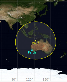
According to Gpredict, and assuming the highly circular ~1450km altitude of AO-7 hadn’t decayed much, and that the very
simple electronics
of AO-7 survived the EMP (if there was a nuclear war in the Mad Max
universe), then AO-7 in it’s VHF/UHF mode would be a good candidate to talk to Indonesia, Papua New Guinea, and of course the whole of Australia from the supposed Western Australia location of the
characters.
Mad Max commsat coverage
Link Budget shouldn’t be an issue, with a rubber duck antenna and 4 Watt satellite, it’s possible now, how much more so when there are very few anthropogenic signals about.
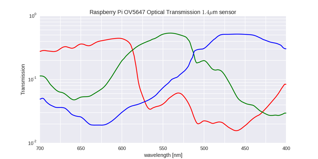
I took the data
digitized from the OV5647 datasheet
by Koen Hufkens and put it into HDF5 format and provided a convenient reading/plotting Python program so that others can use it.
Naturally, individual cameras vary, and the spectral response extends beyond that shown here.
“The Design of CMOS Radio-Frequency Integrated Circuits” by Thomas Lee.
Written in inimitable affable style.
Expects knowledge of discrete RF circuits and teaches you how to make ICs.
High used price testament to staying power.
Thanks to more great support from the SRI Sondrestrom team and of course NSF, we are once again observing with the amazing Marshall 140mm lens and the Andor Neo sCMOS camera.
This gives up to 8 degree field of view with up to hundreds of frames per second.
We are starting off with white-light (unfiltered) operations, but will soon transition to a “prompt emissions” BG3 filter to avoid the smearing that happens in high-speed auroral video from long-lifetime metastable emissions.
DMC experimental data
collected funded by the National Science Foundation and AFOSR sponsored auroral observation instrument:
Dual-Scale Multi Camera (DMC).
Data is generally sorted into folders by date.
Remember to check +/- 1 day from your desired date if you don’t see the data you’re looking for.
The UTC/UT1 times specified in these files are estimates.
Error in timing may be as large as a minute for data files in the 2012-2013 seasons because the observations were not hardware-timed.
2015-2016 season:
Only the Neo is on site, first installed/focused without BG3 filter on Oct 19 2015, although the filter is available on-site.
2012-2013 season:
The cameras were installed under a flat plate of glass, as a dome caused massive distortions in the narrow field image
This procedure assumes that two or more encrypted Comtrend G.hn powerline Ethernet units are already working on G.hn profile “PLC 50MHz with MIMO”, and another unit is being added.
This can be done on any operating system with an Ethernet adapter and web browser.
Set the PC Ethernet adapter (temporarily) to a static IP of 192.168.0.6, subnet 255.255.255.0. A gateway or DNS is not required.
Browse to the factory default IP address in a web browser: 192.168.0.5. The default password is admin.
Keep this browser window open, and open a second window.
Unplug the new G.hn unit, and connect the laptop to the primary G.hn unit via Ethernet.
Browse to the primary G.hn IP address (perhaps 192.168.0.5) and click Pair. This makes the primary ready to accept new units.
Plug in via Ethernet to the new G.hn and click Pair. It will promptly require a login again, click Pair and refresh. The same random “domain name”, “pairing password” and “Domain ID DOD” as the primary should be visible.
Plug the primary Ethernet back into the network as it was before. The middle green light should go back on.
On the new unit, the top and bottom green lights should be steady green, with the middle light flickering with Ethernet activity.
Return the PC Ethernet to its previous configuration (probably DHCP). Browsing the web over the new G.hn connection should be possible after resetting the Ethernet adapter (or unplugging/plugging).
Troubleshooting:
Ensure the primary unit (the one connected to the actual hardwired Ethernet Internet connection) has node type DOMAIN_MASTER.
Ensure all other G.hn units have node type END_POINT.
Avoid using power strips or surge suppressors on the power outlets. The units will only work when plugged directly into a wall outlet (GFCI is OK).
Only use G.hn profile “PLC 50MHz with MIMO” as this provides maximum range with multiple breaker panels in large houses, since it uses all three powerline wires.
NDIM mode should be automatic; after pairing, it will be on the same Domain ID DOD.
Use G.hn encryption to prevent unauthorized access to the network from an outlet on the outside (or inside) of the house.
Consider setting each device to a unique IPv4 manual address. This allows access to other G.hn adapter configuration pages via a web browser when directly connected to one of them.
The manually set IPv4 should NOT be on the same subnet as the network. For some reason, it just won’t work.
Upgrading firmware:
At the time of writing, a Windows 7 PC is required as newer Windows versions are not supported yet.
Errors will occur if not using Windows 7.
A virtual machine of Windows 7 did not work; it had to be a bare metal Windows 7 installation.
Java installation is also required.
It may be necessary to try once or twice, and try resetting power to the PG-9172.
Resetting to factory defaults may also help.
Upgrading firmware should work after 1-2 tries.
This cannot be done remotely; direct connection to the Ethernet jack of the PG-9172 from the Windows 7 PC is required to upgrade Comtrend PG-9172 firmware.
Consider disabling Intel RapidStart to avoid problems resuming from sleep.
RapidStart enables a deeper S4 sleep state, transitioning from an initial S3 state.
However, this transition can be buggy.
If the PC is not always able to resume from sleep/suspend, try disabling RapidStart.
Consider disabling hibernation if resuming from hibernation is not needed.
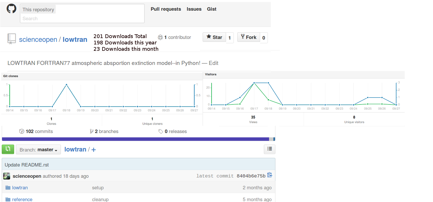
Update Sept 2016 Github has changed their user front pages, moving a little toward this direction.
As submitted to Github:
I advocate to scientist/engineering colleagues and at the legislative level to encourage collaborative open-source development on everything from smart transportation and robotics to climate change modeling and data analysis.
The effort to sunshine code out of dusty forgotten hard drives and into the light would be significantly enhanced if Github would by default or prominently, easily selectable option show repo traffic (views, clones, download zip).
The civic and scientific value of this change could be surprising, and is seemingly something a couple talented interns could prototype in a few weeks.
Github, please help us make a better world of open code by incentivizing authors via easy intuitive plots of repo traffic.
Obtaining a PC that is suitable for high speed camera/SDR work typically entails building a PC from parts for $1K, or getting an appropriate off the shelf Dell Precision for $2.5K.
A desktop CPU is needed with a moderate amount of CPU cache memory and a motherboard with sufficient PCIe slots for the data acquisition cards used.
Some equipment such as software defined radio (SDR) requires dual 10-Gig Ethernet via a PCIe card, and some cameras require a CameraLink PCIe card.
Other devices with onboard FPGAs sometimes require USB 3.0 or Thunderbolt connections.
Don’t use USB 3.0 hubs between PC and the device!
For high frame rate camera acquisition, here are a few CPU series that are known to work well via lab experiment.
The “extreme” edition or Xeon CPUs are not necessary (unless the manufacturer specifies).
Note all these CPUs have at least 8MB of L3 cache (on the CPU die) and are vPro capable.
Please only use desktop quad core i7 CPUs with model number NOT ending in “U”.
Please consider avoiding:
“ultrabook” Intel CPUs that have a model number ending in “U”, such as the Intel NUCs presently use.
laptop computers or tablet computers.
CPUs with model ending in “K” as currently, overclockable CPUs don’t have Intel vPro remote management
Get a motherboard supporting vPro with no less than four USB 3.0 ports.
It’s not wise to cascade USB 3.0 hubs.
Four USB 3.0 seven-port hubs allow up to 28 USB 3.0 HDD, to get hundreds of TB of external storage.
That’s enough storage for 3 months of 12 hour recording per day, or far longer (years) if filtering out unneeded data off-line.
This example assumes use of Andor Solis (paid software), which provides the drivers for the Neo.
Free open-source
MicroManager
can be used with the Andor sCMOS cameras after installing Andor’s free driver pack for MicroManager.
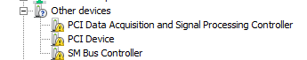
If the Neo drivers or Neon Bitflow CameraLink drivers are missing, Windows Device Manager will look like:
Windows Device manager without driver for Andor Neo
“PCI Device” is the Neon Bitflow card.
“PCI Data Acquisition and Signal Processing Controller” is the National
Instrument X-series card.
“SM Bus controller” is just the motherboard and is a common sight in
some PCs.
While installing the drivers via Solis or the Driver Pack, approve driver installs then reboot the PC when they’re done.
Windows Device Manager after rebooting will look like:
Windows Device manager with driver working for Andor Neo
First powerup and use of Andor Neo/Zyla:
Power on the Neo
startup Solis
Observe the camera serial number in the title bar.
Turn on the Neo before starting Solis/MicroManager!
If problem, close Solis / MicroManager, power on the sCMOS camera, and then reopen Solis/MicroManager.